
The On-Board Diagnostics (OBD2) system in your vehicle is more than just a connection port; it’s a gateway to understanding your car’s health and performance. If you’ve ever wondered What Can You Do With Car Diagnostics Obd2, this comprehensive guide is for you. We’ll delve into the practical applications of OBD2, explaining how it empowers you to diagnose issues, monitor real-time data, and even enhance your driving experience.
This guide provides a practical introduction to the OBD2 protocol, covering everything from the OBD2 connector and Parameter IDs (PIDs) to its link with the CAN bus. Whether you’re a car enthusiast, a DIY mechanic, or simply curious about your vehicle’s inner workings, understanding OBD2 unlocks a wealth of possibilities.
Learn why this has become a go-to resource for understanding what can you do with car diagnostics OBD2.
In this article
Author: Martin Falch (updated January 2025)
Download as PDF
Understanding the Basics: What is OBD2 and Why Does it Matter?
OBD2, short for On-Board Diagnostics version 2, is essentially your car’s self-diagnostic system. It’s a standardized protocol mandated in most modern vehicles, designed to monitor and report on various aspects of your car’s operation. At its core, OBD2 allows you to access Diagnostic Trouble Codes (DTCs) and real-time data through a standardized OBD2 connector.
You’ve likely encountered OBD2 in action without even realizing it. That “check engine light” or malfunction indicator light (MIL) illuminating on your dashboard? That’s OBD2 at work, signaling that your car has detected a potential issue.
When you take your vehicle to a mechanic for a check-up, one of the first things they do is connect an OBD2 scanner. This tool plugs into the OBD2 16-pin connector, typically located under the dashboard near the steering wheel. The scanner sends ‘OBD2 requests’ to your car’s computer, and the car responds with ‘OBD2 responses’. These responses contain valuable information such as speed, fuel level, and, crucially, Diagnostic Trouble Codes (DTCs). This data empowers mechanics (and you!) to efficiently troubleshoot problems and understand what’s going on under the hood using car diagnostics OBD2.
Understanding OBD2: The Malfunction Indicator Light (MIL) or Check Engine Light signals when your car’s self-diagnostic system detects an issue.
Does Your Car Have OBD2? Checking for Compatibility
The question of OBD2 compatibility is usually straightforward: If your car is relatively new, it probably supports OBD2. The vast majority of non-electric cars manufactured in recent decades are OBD2 compliant, and many utilize the CAN bus communication protocol.
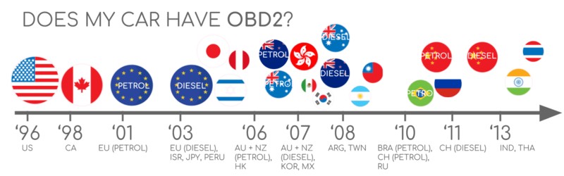
However, it’s worth noting that the presence of a 16-pin OBD2 connector doesn’t guarantee full OBD2 compliance, particularly in older vehicles. To ascertain whether your car is truly OBD2 compliant, consider its origin and year of purchase:
OBD2 Compliance Guide: Check your vehicle’s origin and year of purchase to determine OBD2 compatibility.
A Brief History of OBD2: From Emissions to Everyday Diagnostics
The journey of OBD2 began in California, driven by the California Air Resources Board (CARB). In the early 1990s, CARB mandated OBD in all new vehicles starting from 1991 to monitor and control vehicle emissions.
The Society of Automotive Engineers (SAE) played a crucial role in standardizing the protocol, leading to the development of OBD2. This standardization encompassed Diagnostic Trouble Codes (DTCs) and the OBD connector itself (SAE J1962), ensuring consistency across different vehicle manufacturers.
The implementation of the OBD2 standard was a phased process, rolled out progressively over the years:
- 1996: OBD2 became mandatory in the USA for all cars and light trucks.
- 2001: The European Union mandated OBD2 for gasoline cars.
- 2003: The EU extended the mandate to diesel cars (EOBD).
- 2005: OBD2 compliance was required in the US for medium-duty vehicles.
- 2008: US vehicles were required to adopt ISO 15765-4 (CAN) as the foundation for OBD2 communication.
- 2010: OBD2 became mandatory for heavy-duty vehicles in the US.
OBD2 Historical Timeline: From emission control origins to widespread adoption across vehicle types and regions.
OBD2 Timeline: A visual overview of the key milestones in the development and implementation of On-Board Diagnostics.
OBD3 and the Future: Anticipating remote diagnostics, emissions testing, cloud integration, and the Internet of Things (IoT) in vehicle diagnostics.
The Future of OBD2: Trends and Potential Shifts
OBD2’s role in vehicle diagnostics is firmly established, but its future is dynamic and subject to evolving trends.
Originally conceived for emissions monitoring and testing, legislative OBD2 faces new considerations, particularly with the rise of electric vehicles (EVs). Interestingly, electric vehicles are not currently mandated to support OBD2 in its traditional form. This is reflected in the fact that most modern EVs do not support standard OBD2 requests. Instead, they often utilize OEM-specific UDS communication protocols. This shift generally restricts access to EV data unless decoding rules are reverse-engineered. However, there are successful cases of reverse engineering, as illustrated in studies for electric car brands like Tesla, Hyundai/Kia, Nissan, and VW/Skoda EVs.
Current OBD2 implementations also have limitations in data richness and lower-layer protocols. To address these, modern alternatives like WWH-OBD (World Wide Harmonized OBD) and OBDonUDS (OBD on UDS) have emerged. These protocols aim to enhance OBD communication by using the UDS protocol as a foundation. For a deeper dive into these advancements, refer to introductions to UDS.
In our increasingly connected world, traditional OBD2 testing methods can seem outdated. Manual emission control checks are time-consuming and costly. The proposed solution? OBD3 – integrating telematics into all vehicles.
OBD3 envisions adding a small radio transponder to vehicles, similar to those used for bridge tolls. This would enable vehicles to transmit their vehicle identification number (VIN) and DTCs wirelessly to a central server for automated checks. Many existing devices already facilitate CAN or OBD2 data transfer via WiFi/cellular networks, such as the CANedge2 WiFi CAN logger and the CANedge3 3G/4G CAN logger. While offering convenience and cost savings, OBD3 raises political and privacy concerns related to surveillance.
The original purpose of OBD2 was for stationary emission controls. However, today, third parties extensively utilize OBD2 to generate real-time data through OBD2 dongles, CAN loggers and similar tools. However, the German automotive industry is exploring potential changes that could impact this trend.
The industry is considering “turning off” OBD2 functionality during driving and instead centralizing data collection within manufacturer servers. This shift would grant manufacturers greater control over automotive big data. Arguments for this change often cite security benefits, such as reducing the risk of car hacking. However, many view this as a commercially motivated move. Whether this becomes a widespread trend remains to be seen, but it could significantly disrupt the market for third-party OBD2 services.
Future Challenges for OBD2: Electric vehicles and potential limitations on data access.
Enhance Your Understanding with Our ‘Ultimate CAN Guide’
Eager to become a CAN bus expert?
Our comprehensive 160+ page PDF combines 12 ‘simple intros’ into one resource:
Download now
OBD2 Standards: Defining Communication
On-board diagnostics, or OBD2, operates as a higher-layer protocol, similar to a language, while CAN functions as the communication method, akin to a telephone line. This analogy positions OBD2 alongside other CAN-based higher-layer protocols like J1939, CANopen, and NMEA 2000.
Specifically, OBD2 standards define the OBD2 connector, lower-layer protocols, OBD2 Parameter IDs (PIDs), and other crucial aspects of the diagnostic communication.
These standards can be mapped onto a 7-layer OSI model. The following sections will highlight the most critical standards. Within the OSI model framework, you’ll notice that SAE and ISO standards cover multiple layers. This reflects the development of OBD standards in both the USA (SAE) and the EU (ISO). Many of these standards are technically very similar, for example, SAE J1979 and ISO 15031-5, as well as SAE J1962 and ISO 15031-3.
OBD2 and CAN Bus in the OSI Model: Illustrating the layered architecture of OBD2 communication over CAN.
OBD2 Connector Pinout: Type A Data Link Connector (DLC) socket diagram.
The OBD2 Connector [SAE J1962 / ISO 15031-3]: Your Access Point
The 16-pin OBD2 connector serves as the physical interface for accessing your car’s diagnostic data. Defined by the SAE J1962 / ISO 15031-3 standard, this connector provides a standardized way to interact with your vehicle’s systems.
The illustration above shows a typical Type A OBD2 pin connector, also known as a Data Link Connector (DLC). Key aspects to note about the OBD2 connector include:
- Its location is generally near the steering wheel, although it may be hidden from plain sight.
- Pin 16 provides battery power, often even when the ignition is off, allowing for diagnostics without the engine running.
- The OBD2 pinout configuration varies depending on the communication protocol used by the vehicle.
- CAN bus is the most prevalent lower-layer protocol, meaning pins 6 (CAN-H) and 14 (CAN-L) are frequently connected for data transmission.
OBD2 Connector Types: A vs. B
You might encounter both Type A and Type B OBD2 connectors. Type A is commonly found in cars and light-duty vehicles, while Type B is more prevalent in medium and heavy-duty vehicles.
As shown, both types have similar OBD2 pinouts but differ in power supply output: Type A typically provides 12V, and Type B provides 24V. Baud rates can also vary, with cars often using 500K and heavy-duty vehicles frequently using 250K (though 500K support is increasing).
Visually distinguishing them is straightforward: the Type B OBD2 connector has an interrupted groove in the middle. This physical difference means a Type B OBD2 adapter cable is compatible with both Type A and Type B sockets, while a Type A adapter will not fit into a Type B socket.
OBD2 Connector Types A and B: Distinguishing features, voltage differences, and applications in cars, vans, and trucks.
OBD2 and CAN Bus Relationship: Illustrating how OBD2 protocols operate over the CAN bus.
OBD2 and CAN Bus [ISO 15765-4]: The Communication Foundation
Since 2008, CAN bus has been the mandatory lower-layer protocol for OBD2 in all vehicles sold in the US, as per ISO 15765.
ISO 15765-4, also known as Diagnostics over CAN (DoCAN), specifies a set of constraints applied to the CAN standard (ISO 11898). It standardizes the CAN interface for diagnostic equipment, focusing on the physical, data link, and network layers:
- CAN bus bit-rate must be either 250K or 500K.
- CAN IDs can be 11-bit or 29-bit.
- Specific CAN IDs are designated for OBD requests and responses.
- Diagnostic CAN frame data length is fixed at 8 bytes.
- The OBD2 adapter cable must not exceed 5 meters in length.
OBD2 CAN Identifiers (11-bit, 29-bit): Addressing Communication
OBD2 communication is built upon request/response message exchanges.
In most cars, 11-bit CAN IDs are used for OBD2. The ‘Functional Addressing’ ID, 0x7DF, is used to query all OBD2-compatible ECUs for data related to a requested parameter (defined in ISO 15765-4). ‘Physical Addressing’ requests to specific ECUs use CAN IDs ranging from 0x7E0 to 0x7E7, though this is less common.
ECUs respond using 11-bit IDs in the range 0x7E8-0x7EF. The most frequent response ID is 0x7E8 (Engine Control Module, ECM), followed by 0x7E9 (Transmission Control Module, TCM).
In some vehicles, particularly vans and medium to heavy-duty vehicles, OBD2 communication may utilize extended 29-bit CAN identifiers instead of 11-bit IDs. In these cases, the ‘Functional Addressing’ CAN ID is 0x18DB33F1. Responses are sent with CAN IDs ranging from 0x18DAF100 to 0x18DAF1FF (typically 18DAF110 and 18DAF11E). The response ID is also sometimes represented in the ‘J1939 PGN’ format, specifically PGN 0xDA00 (55808), which is marked as ‘Reserved for ISO 15765-2’ in the J1939-71 standard.
OBD2 Request and Response Frames: Illustrating the structure of OBD2 communication over CAN.
OBD2 vs. Proprietary CAN Protocols: Highlighting the difference between standardized OBD2 data and manufacturer-specific CAN data within a vehicle.
OBD2 vs. Proprietary CAN Protocols: Understanding the Difference
It’s crucial to understand that your car’s Electronic Control Units (ECUs) operate using proprietary CAN protocols implemented by the Original Equipment Manufacturer (OEM), independently of OBD2. These OEM-specific CAN protocols are often unique to the vehicle’s brand, model, and year. Unless you are the OEM or can reverse engineer these protocols, this data remains largely inaccessible and undecipherable.
Connecting a CAN bus data logger to your car’s OBD2 connector may reveal OEM-specific CAN data, typically transmitted at high rates (1000-2000 frames/second). However, many newer vehicles employ a ‘gateway’ that restricts access to this OEM CAN data through the OBD2 port, allowing only OBD2 communication.
In essence, OBD2 functions as an ‘additional’ higher-layer protocol operating alongside the OEM-specific protocol.
Bit-rate and ID Validation: Ensuring Correct Communication
OBD2 can utilize two bit-rates (250K, 500K) and two CAN ID lengths (11-bit, 29-bit), resulting in four possible combinations. Modern vehicles most commonly use 500K and 11-bit IDs, but external diagnostic tools should systematically verify the correct combination for reliable communication.
ISO 15765-4 provides guidelines for a systematic initialization sequence to determine the appropriate combination, as illustrated in the flowchart below. This process relies on the fact that OBD2-compliant vehicles must respond to a specific mandatory OBD2 request (see the OBD2 PID section for details) and that transmitting data at an incorrect bit-rate will generate CAN error frames.
Newer versions of ISO 15765-4 acknowledge that vehicles may support OBD communication via OBDonUDS (OBD on Unified Diagnostic Services) rather than OBDonEDS (OBD on Emission Diagnostic Service). This article primarily focuses on OBD2/OBDonEDS (defined by ISO 15031-5/SAE J1979) as opposed to WWH-OBD/OBDonUDS (defined by ISO 14229, ISO 27145-3/SAE J1979-2).
To distinguish between OBDonEDS and OBDonUDS protocols, diagnostic tools may send additional request messages, specifically UDS requests with 11-bit/29-bit functional address IDs for service 0x22 and data identifier (DID) 0xF810 (protocol identification). Vehicles supporting OBDonUDS should have ECUs that respond to this DID.
In practice, OBDonEDS (also known as OBD2, SAE OBD, EOBD, or ISO OBD) is prevalent in most non-EV cars today, while WWH-OBD is mainly used in EU trucks and buses.
OBD2 Bit-rate and CAN ID Validation Flowchart: A systematic approach to determine the correct communication parameters.
OBD2 Lower-Layer Protocols: The five primary protocols used for OBD2 communication, including CAN, KWP2000, ISO9141, and SAE J1850 (VPW & PWM).
Five Lower-Layer OBD2 Protocols: Beyond CAN
While CAN (ISO 15765) is now the dominant lower-layer protocol for OBD2 in most vehicles, particularly those manufactured post-2008, it’s valuable to be aware of the other four protocols used in older vehicles. Examining the OBD2 connector pinouts can sometimes help identify which protocol your older car might be using.
- ISO 15765 (CAN bus): Mandatory in US cars since 2008 and widely used today.
- ISO14230-4 (KWP2000): Keyword Protocol 2000, common in 2003+ vehicles, especially in Asia.
- ISO 9141-2: Used in EU, Chrysler, and Asian cars during 2000-2004.
- SAE J1850 (VPW): Predominantly used in older General Motors (GM) vehicles.
- SAE J1850 (PWM): Primarily found in older Ford vehicles.
Transporting OBD2 Messages via ISO-TP [ISO 15765-2]: Handling Larger Data
All OBD2 data transmission over CAN bus relies on the ISO-TP (ISO 15765-2) transport protocol. This protocol enables the communication of data payloads exceeding the 8-byte limit of a standard CAN frame. ISO-TP is essential for OBD2 functions like retrieving the Vehicle Identification Number (VIN) or Diagnostic Trouble Codes (DTCs), which often require more than 8 bytes of data. It manages segmentation, flow control, and reassembly of these larger messages. For more in-depth information, consult introductions to UDS.
However, many OBD2 data exchanges fit within a single CAN frame. In these cases, ISO 15765-2 specifies the use of ‘Single Frame’ (SF) formatting. The first data byte (PCI field) indicates the payload length (excluding padding), leaving 7 bytes for OBD2 communication.
ISO-TP Frame Types for OBD2: Single Frame (SF), First Frame (FF), Consecutive Frame (CF), and Flow Control (FC) types defined in ISO 15765-2.
The OBD2 Diagnostic Message [SAE J1979, ISO 15031-5]: Anatomy of a Request and Response
To better understand OBD2 communication over CAN, let’s examine a raw ‘Single Frame’ OBD2 CAN message. In simplified terms, an OBD2 message comprises an identifier, a data length indicator (PCI field), and the data itself. The data section is further structured into Mode, Parameter ID (PID), and data bytes.
OBD2 Message Structure: Breakdown of a raw OBD2 CAN frame, including Mode, PID, and data bytes.
Example: OBD2 Request and Response in Action
Consider this practical example of requesting and receiving ‘Vehicle Speed’ data.
An external tool sends a request message to the car using CAN ID 0x7DF with a 2-byte payload: Mode 0x01 and PID 0x0D. The car responds using CAN ID 0x7E8 with a 3-byte payload, including the Vehicle Speed value in the 4th byte, which is 0x32 (decimal 50).
By consulting OBD2 PID documentation for PID 0x0D, we find that this value corresponds to a physical value of 50 km/h.
Let’s now explore OBD2 modes and PIDs in more detail.
OBD2 Request and Response Example: Request for Vehicle Speed (PID 0x0D) and the corresponding response.
OBD2 PID 0x0D – Vehicle Speed: Detailed explanation of the Vehicle Speed Parameter ID and its data representation.
OBD2 Services (Modes): Overview of the 10 standardized OBD2 diagnostic services or modes.
The 10 OBD2 Services (Modes): Accessing Different Diagnostic Functions
OBD2 defines 10 diagnostic services, often referred to as modes. Mode 0x01 is used to retrieve current real-time data parameters, while other modes are designed for accessing and clearing Diagnostic Trouble Codes (DTCs) or retrieving freeze frame data.
It’s important to note that not all vehicles are required to support all 10 OBD2 modes. Furthermore, manufacturers may implement additional modes beyond the 10 standardized ones, known as OEM-specific OBD2 modes.
In OBD2 messages, the mode is located in the second byte of the data payload. In a request message, the mode is included directly (e.g., 0x01). In a response message, 0x40 is added to the requested mode (e.g., resulting in 0x41 for a response to mode 0x01).
OBD2 Parameter IDs (PIDs): Requesting Specific Data
Within each OBD2 mode, Parameter IDs (PIDs) are used to specify the particular data you wish to access.
For example, Mode 0x01 encompasses approximately 200 standardized PIDs that provide real-time data on parameters like speed, RPM, and fuel level. However, a vehicle is not obligated to support every PID within a given mode. In practice, most vehicles support only a subset of the available PIDs.
Among these PIDs, one is particularly significant:
If an emissions-related ECU supports any OBD2 services at all, it must support Mode 0x01 PID 0x00. Responding to this PID, the vehicle ECU indicates whether it supports PIDs 0x01-0x20. This makes PID 0x00 a fundamental tool for ‘OBD2 compatibility testing’. Similarly, PIDs 0x20, 0x40, …, 0xC0 can be used to determine support for subsequent ranges of Mode 0x01 PIDs.
OBD2 Request and Response Frames: Reiterating the structure of OBD2 communication with focus on PID usage.
OBD2 PID Overview Tool: A helpful resource for exploring and understanding OBD2 Parameter IDs.
Tip: Utilizing an OBD2 PID Overview Tool
The appendices of SAE J1979 and ISO 15031-5 contain scaling information for standard OBD2 PIDs, enabling you to convert raw data into meaningful physical values, as detailed in introductions to CAN bus.
For quick lookups of Mode 0x01 PIDs, consider using an OBD2 PID overview tool. This tool assists in constructing OBD2 request frames and dynamically decoding OBD2 responses.
OBD2 PID overview tool
Practical Guide: How to Log and Decode OBD2 Data
This section provides a practical walkthrough of logging OBD2 data using a CANedge CAN bus data logger.
The CANedge’s configurable CAN frame transmission capabilities make it suitable for OBD2 logging.
Connecting the CANedge to your vehicle is straightforward using an OBD2-DB9 adapter cable.
OBD2 Data Logging Setup: Illustrating the connection of an OBD2 data logger to a vehicle’s OBD2 port.
Validating Bit-rate: Sending a CAN frame at a specific bit-rate (e.g., 500K) to confirm successful transmission.
Reviewing Supported PIDs in asammdf: Examining responses to ‘Supported PIDs’ requests using asammdf software.
Step #1: Bit-rate, ID, and Supported PID Validation
As discussed, ISO 15765-4 outlines how to determine the correct bit-rate and IDs for a specific vehicle. You can perform these tests using a CANedge as follows (refer to the CANedge Intro for detailed instructions):
- Transmit a CAN frame at 500K and verify successful transmission (if unsuccessful, try 250K).
- Use the identified bit-rate for subsequent communication.
- Send multiple ‘Supported PIDs’ requests and analyze the responses.
- Determine 11-bit or 29-bit CAN ID usage based on response IDs.
- Identify supported PIDs based on response data.
Pre-configured settings are available to simplify these tests.
Most non-EV cars manufactured in 2008 or later support 40-80 PIDs using a 500K bit-rate, 11-bit CAN IDs, and the OBD2/OBDonEDS protocol.
As illustrated in the asammdf GUI screenshot, receiving multiple responses to a single OBD request is common. This is because using the 0x7DF request ID polls all ECUs for responses. Since all OBD2/OBDonEDS-compliant ECUs must support service 0x01 PID 0x00, numerous responses to this PID are typical. Subsequent ‘Supported PIDs’ requests generally elicit fewer ECU responses. Notably, the ECM ECU (0x7E8) often supports all PIDs supported by other ECUs in the example, suggesting that busload can be reduced by directing subsequent requests specifically to this ECU using ‘Physical Addressing’ CAN ID 0x7E0.
Step #2: Configuring OBD2 PID Requests for Logging
Once you’ve identified the supported OBD2 PIDs, bit-rate, and CAN IDs for your vehicle, you can configure your transmit list to request the PIDs of interest for logging.
Consider these factors when setting up your PID requests:
- CAN IDs: Switch to ‘Physical Addressing’ request IDs (e.g., 0x7E0) to minimize redundant responses.
- Spacing: Introduce a delay of 300-500 ms between OBD2 requests to prevent ECU overload and ensure reliable responses.
- Battery Drain: Implement triggers to stop transmissions when the vehicle is inactive, preventing unnecessary ECU wake-up and battery drain.
- Filters: Apply filters to record only OBD2 responses if your vehicle also transmits OEM-specific CAN data, streamlining your data logs.
With these configurations in place, your data logger is ready to record raw OBD2 data.
Example CANedge OBD2 PID Request List: Configuration example showing a list of OBD2 PID requests for a CANedge data logger.
Visualizing Decoded OBD2 Data: asammdf software displaying DBC decoded and visualized OBD2 data.
Step #3: DBC Decoding of Raw OBD2 Data
To analyze and visualize your logged data, you need to decode the raw OBD2 data into ‘physical values’ like km/h or °C.
Decoding information is available in ISO 15031-5/SAE J1979 and online resources like Wikipedia. For convenience, a free OBD2 DBC file is available, simplifying DBC decoding of raw OBD2 data in most CAN bus software tools.
Decoding OBD2 data is somewhat more intricate than decoding standard CAN signals. This is because different OBD2 PIDs are transmitted using the same CAN ID (e.g., 0x7E8). Therefore, the CAN ID alone is insufficient to uniquely identify the signals within the payload.
To resolve this, you must consider the CAN ID, OBD2 mode, and OBD2 PID to identify each signal. This is a form of multiplexing known as ‘extended multiplexing‘, which can be implemented using DBC files.
CANedge: Your OBD2 Data Logger Solution
The CANedge offers a user-friendly solution for recording OBD2 data directly to an 8-32 GB SD card. Simply connect it to your vehicle to start logging, and utilize free software/APIs and the provided OBD2 DBC for data decoding.
OBD2 logger intro
CANedge Product Page
OBD2 Multi-Frame Examples [ISO-TP]: Handling Larger Messages
All OBD2 communication utilizes the ISO-TP (transport protocol) as defined in ISO 15765-2. While most examples have focused on single-frame communication, multi-frame communication is necessary for larger data sets.
Multi-frame OBD2 communication requires flow control frames (refer to introductions to UDS). In practice, this can be achieved by transmitting a static flow control frame approximately 50 ms after the initial request frame, as demonstrated in the CANedge configuration example.
Furthermore, processing multi-frame OBD2 responses requires CAN software/API tools with ISO-TP support, such as the CANedge MF4 decoders.
OBD2 Multi-Frame Request Example: Requesting the Vehicle Identification Number (VIN) using a multi-frame message.
Example 1: Retrieving the OBD2 Vehicle Identification Number (VIN)
The Vehicle Identification Number (VIN) is crucial for telematics, diagnostics, and various other applications (see introductions to UDS for more information). To retrieve the VIN using OBD2 requests, use Mode 0x09 and PID 0x02:
The tester tool initiates a Single Frame request with the PCI field (0x02), request service identifier (0x09), and PID (0x02).
The vehicle responds with a First Frame containing the PCI, length (0x014 = 20 bytes), mode (0x49, i.e., 0x09 + 0x40), and PID (0x02). Following the PID is byte 0x01, representing the Number Of Data Items (NODI), which is 1 in this case (refer to ISO 15031-5 / SAE J1979 for detailed specifications). The subsequent 17 bytes constitute the VIN, which can be converted from HEX to ASCII using methods described in introductions to UDS.
Example 2: OBD2 Multi-PID Request (6x) – Advanced Data Acquisition
External tools can request up to 6 Mode 0x01 OBD2 PIDs within a single request frame. The ECU will respond with data for supported PIDs (excluding unsupported ones), potentially using multi-frame responses via ISO-TP if necessary.
This advanced feature enhances data collection frequency and efficiency. However, it also makes signal encoding request-specific, complicating the use of generic OBD2 DBC files. This method is generally not recommended for practical use. Below is an example trace illustrating this approach:
The multi-frame response is similar to the VIN example but includes the requested PIDs alongside their corresponding data. The PIDs in the example are ordered similarly to the request order, which is common but not strictly mandated by ISO 15031-5.
Decoding such responses using generic DBC files is challenging. Therefore, this approach is not recommended for practical data logging unless you are using specialized tools with built-in support. Effectively, you would be dealing with extended multiplexing with multiple instances throughout the payload. Furthermore, generalizing DBC files across vehicles with varying supported PIDs becomes extremely difficult. Handling this via pure DBC manipulations becomes nearly impossible when sending multiple multi-PID requests, as there is no straightforward way to differentiate these messages.
Workarounds might involve custom scripts that interpret response messages in conjunction with request messages, but these are generally difficult to scale and manage.
Example 3: OBD2 Diagnostic Trouble Codes (DTCs) – Identifying Vehicle Issues
OBD2 enables requesting emissions-related Diagnostic Trouble Codes (DTCs) using Mode 0x03, ‘Show stored Diagnostic Trouble Codes.’ No PID is included in the request. The target ECU(s) will respond with the number of stored DTCs (possibly 0 if none are present), with each DTC occupying 2 data bytes. Multi-frame responses are necessary when more than 2 DTCs are stored.
The 2-byte DTC value is typically structured as per ISO 15031-5/ISO 15031-6. The first 2 bits define the ‘category,’ and the remaining 14 bits form a 4-digit code (displayed in hexadecimal), as shown below. Decoded DTC values can be looked up using OBD2 DTC lookup tools like repairpal.com.
The example below shows a request to an ECU with 6 stored DTCs.
OBD2 DTC Decoding: Illustrating how to interpret and decode Diagnostic Trouble Codes from OBD2 data.
Real-World Applications: OBD2 Data Logging Use Cases
OBD2 data from cars and light trucks has diverse applications across various sectors:
Vehicle Data Logging
OBD2 data logging in cars can be used to optimize fuel efficiency, improve driving habits, test prototype components, and for insurance purposes.
OBD2 Logger Solutions
Real-time Vehicle Diagnostics
OBD2 interfaces enable real-time streaming of vehicle data for immediate diagnostics, aiding in troubleshooting vehicle issues and performance monitoring.
OBD2 Real-time Streaming
Predictive Maintenance
IoT-enabled OBD2 loggers facilitate cloud-based vehicle monitoring for predictive maintenance, helping to anticipate and prevent breakdowns in cars and light trucks.
Predictive Maintenance Solutions
Vehicle Black Box Recording
An OBD2 logger can serve as a ‘black box’ for vehicles or equipment, providing crucial data for incident analysis, insurance claims, and diagnostic purposes.
CAN Bus Black Box Loggers
Do you have an OBD2 data logging application in mind? Contact us for a free consultation!
Contact Us
Explore our guides section for more introductions, or download our comprehensive ‘Ultimate Guide’ PDF.
Need to log or stream OBD2 data?
Get your OBD2 data logger today!
Buy Now
Contact Us
Recommended for you
OBD2 DATA LOGGER: EASILY LOG & CONVERT OBD2 DATA
CANEDGE2 – PRO CAN IoT LOGGER
CAN BUS INTERFACE: STREAMING OBD2 DATA WITH SAVVYCAN