Understanding your Volkswagen’s wiring diagram is crucial for troubleshooting and repairs. This guide will explore the differences between early and late Vw Wiring Diagrams, focusing on the key elements to help you navigate the complexities of your Beetle’s electrical system.
Decoding the VW Wiring Diagram
Volkswagen Beetles, particularly those from the early 1970s, often utilize two distinct wiring diagram styles. Understanding these differences is the first step in effectively using them.
Early VW Wiring Diagrams (Pre-1973)
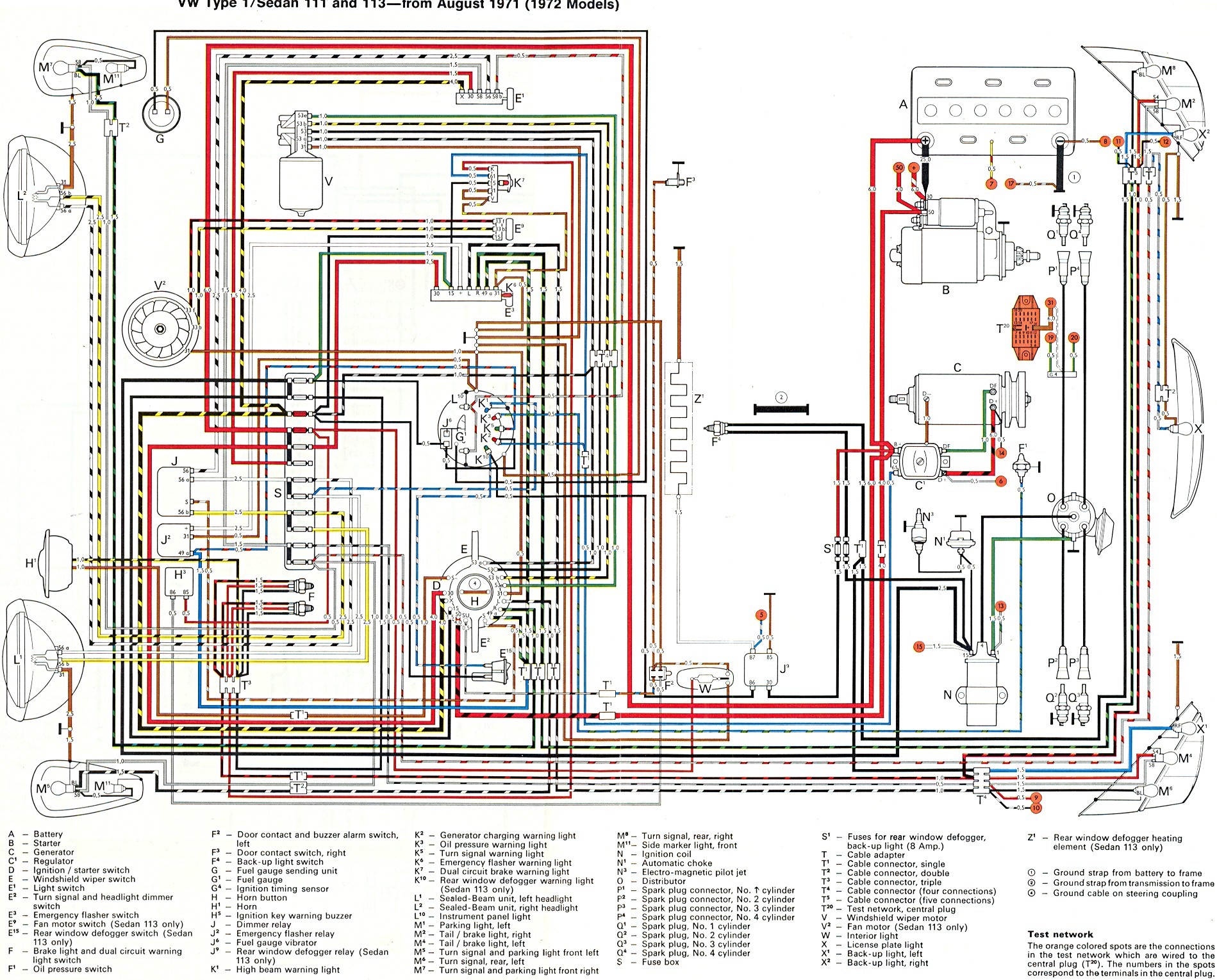
Early diagrams, like those found in 1972 models, visually represent the components’ physical location within the vehicle. Headlights are typically depicted on one end, and taillights on the other. Wires are color-coded and connected to numbered terminals on devices. However, these diagrams don’t illustrate the internal workings of switches, making it challenging to trace the current flow within them.
Example of an early VW wiring diagram (1972)
Later VW Wiring Diagrams (Post-1973)
Later diagrams, introduced around 1973, prioritize circuit functionality over physical component placement. They showcase the flow of current, allowing you to “see” inside switches and understand how wires interconnect. For instance, the turn signal assembly, incorporating turn signals, dimmer switch, and horn, is represented across different sections of the diagram, highlighting individual circuits. This approach facilitates troubleshooting by clearly outlining the electrical pathways. The positive current usually flows from the top of the diagram to a ground at the bottom.
Example of a later VW wiring diagram (1973)
Key for the 1973 VW wiring diagram
Navigating the Fuse Box: Input and Output
A critical aspect of any vw wiring diagram is understanding the fuse box. Fuse boxes have distinct INPUT and OUTPUT sides. The INPUT side receives power from the battery, often indicated by thick black lines connecting one side of multiple fuses, creating a bridge. This allows a single wire to power several fuses. The OUTPUT side distributes power to various circuits, protected by the corresponding fuse.
Identifying the INPUT side is vital. Look for the brass bridges connecting fuse pairs. These bridges are always on the INPUT side. Wiring must respect this arrangement: connect INPUT wires to the INPUT side and OUTPUT wires to the OUTPUT side. Incorrect connections can bypass fuse protection, leading to potential electrical hazards. Remember, some circuits, like the ignition coil (black wire), are not fused from the factory.
A helpful tip: headlight fuses are consistently paired as 3-4 and 5-6. These pairs are always bridged on their INPUT side. This knowledge can help you orient yourself and identify fuse #1 and the INPUT side of the fuse box.
Conclusion
While the transition from location-based to circuit-focused diagrams might seem daunting, understanding the key differences allows you to effectively utilize either type for your VW Beetle. Familiarizing yourself with the symbols, layout, and specifically the INPUT/OUTPUT configuration of the fuse box, will significantly enhance your ability to troubleshoot and maintain your vehicle’s electrical system. Remember to consult the correct diagram for your model year for accurate information.