The J1939 protocol is the standard communication language for heavy-duty vehicles, enabling seamless data exchange between Electronic Control Units (ECUs). A crucial component of this system is the J1939 connector, providing a standardized interface for accessing the network. This article delves into the J1939 Pinout, exploring its different types, pin assignments, and applications.
J1939 Connector Types and Pin Assignments
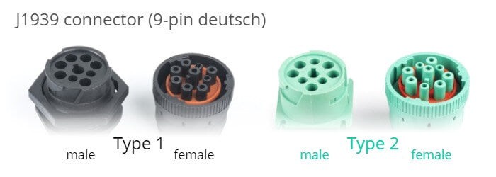
The most common J1939 connector is the 9-pin Deutsch connector, available in two variants:
-
Type 1 (Black): The original connector, predominantly found in older heavy-duty vehicles. Offers CAN communication via pins C (CAN High) and D (CAN Low). May provide access to a secondary J1939 network through pins F and G, or H and J (H: CAN High, J: CAN Low).
-
Type 2 (Green): Introduced in 2013-14 to support higher baud rates (500K). Backwards compatible with Type 1 connectors. Includes a physical keying mechanism to prevent connection with older 250K hardware. Pin assignments are identical to Type 1.
Beyond the standard Deutsch connector, other connector types used with J1939 include:
- J1939 Backbone Connector: A 3-pin Deutsch connector with CAN High, CAN Low, and a shield. Lacks power and ground connections.
- Caterpillar Industrial Connector: A grey 9-pin Deutsch connector with a different pinout (A: Power, B: Ground, F: CAN Low, G: CAN High). Physically blocks standard J1939 connectors.
- OBD2 Type B Connector: Sometimes provides access to the J1939 network via pins 6 and 14.
- Volvo 2013 OBD2 Connector: Similar to the Type B connector, but with additional J1939 access on pins 3 (CAN High) and 11 (CAN Low).
Accessing the J1939 Network via the Connector
The J1939 connector provides a straightforward method for connecting diagnostic tools, data loggers, and other devices to the J1939 network. Utilizing a compatible adapter cable, users can easily tap into the CAN bus through the designated pins, enabling:
- Data Logging: Capturing J1939 data for analysis, fleet management, and predictive maintenance.
- Live Diagnostics: Monitoring real-time vehicle parameters and troubleshooting issues.
- ECU Programming: Updating firmware and configuring ECU settings.
J1939 Pinout and Data Logging
J1939 data loggers, like the CANedge, utilize the connector’s pinout to record raw CAN data. This data can then be decoded using a J1939 DBC file, translating the raw bytes into meaningful information such as engine speed, fuel consumption, and diagnostic trouble codes. This data is instrumental in various applications, including:
- Fleet Management: Optimizing vehicle utilization, reducing fuel costs, and improving driver behavior.
- Predictive Maintenance: Identifying potential vehicle issues before they lead to breakdowns.
- Vehicle Black Box: Providing crucial data for accident reconstruction and liability investigations.
Conclusion
Understanding the J1939 pinout is essential for anyone working with heavy-duty vehicle diagnostics and data logging. The standardized connector and its pin assignments provide a consistent interface for accessing the J1939 network, enabling a wide range of applications that enhance vehicle performance, maintenance, and safety. The availability of different connector types underscores the evolving needs of the industry, accommodating both legacy systems and newer technologies. Choosing the right tools and understanding the connector’s functionality are crucial for successful J1939 data acquisition and analysis.