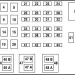
The Detroit Diesel Electronic Control Module (DDEC) IV is a crucial component in managing engine functions in various Detroit Diesel engines. Understanding the Ddec Iv Ecm Pinout is essential for troubleshooting, diagnostics, and repairs. This guide provides a detailed overview of the DDEC IV ECM pinout, enabling technicians and enthusiasts to effectively work with this system.
Understanding the DDEC IV ECM Pinout
The DDEC IV ECM utilizes a complex network of wires and connectors to communicate with various sensors and actuators throughout the engine. Each pin on the ECM connector has a specific function, and knowing these functions is paramount for accurate diagnostics. The pinout diagram provides a roadmap to this intricate network, outlining the purpose of each connection. Accessing a reliable pinout diagram is the first step in effectively troubleshooting any DDEC IV related issues.
Utilizing the Pinout Diagram for Diagnostics
The DDEC IV ECM pinout diagram is an invaluable tool for diagnosing engine problems. By using a multimeter or other diagnostic equipment, technicians can test the voltage and resistance at specific pins to identify faulty sensors, actuators, or wiring issues. For instance, if a particular sensor is malfunctioning, the corresponding pin on the ECM connector will likely exhibit abnormal readings.
Common DDEC IV ECM Issues and Troubleshooting
Several common issues can arise with the DDEC IV ECM, often stemming from faulty wiring, sensor malfunctions, or connector problems. Using the pinout diagram, you can systematically test each connection to pinpoint the root cause. Some frequent problems include:
- Sensor Errors: Issues with sensors like the crankshaft position sensor, camshaft position sensor, or coolant temperature sensor can disrupt engine performance. Referencing the pinout allows for direct testing of these sensor circuits.
- Actuator Problems: Malfunctioning actuators, such as fuel injectors or the EGR valve, can also be diagnosed using the pinout diagram.
- Communication Errors: Problems with the communication lines between the ECM and other engine components can be identified by checking the relevant pins. This is crucial for data transmission and proper engine function.
- Wiring Harness Damage: Damaged or corroded wiring within the harness can lead to various issues. The pinout diagram helps isolate specific wires for testing and repair.
Importance of Accurate Information
When working with the DDEC IV ECM pinout, accuracy is critical. Using an incorrect diagram or misinterpreting the information can lead to misdiagnosis and potentially damage the ECM or other components. Always consult a reliable source for the pinout diagram specific to your engine model and year.
Conclusion
Mastering the DDEC IV ECM pinout is fundamental for anyone working on Detroit Diesel engines equipped with this system. This knowledge empowers technicians to perform accurate diagnostics, efficiently troubleshoot problems, and ensure optimal engine performance. Always remember to use a reliable pinout diagram and exercise caution when testing and repairing electrical components.


