
The Dball2 connector is a critical component for many aftermarket installations in vehicles, particularly those involving remote start or security systems. Understanding its wiring and pinouts is crucial for a successful installation. This guide provides a detailed overview of the dball2 connector, including diagrams, charts, and explanations to simplify the process.
Decoding the dball2 Connector
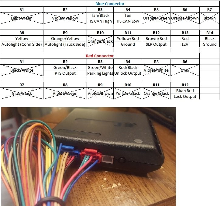
The dball2 connector typically houses several wires, each with a specific function. For custom installations, not all wires are necessary. The diagram below illustrates which wires are commonly used and which can be safely removed. Each pin is identified by its connector color and pin number (e.g., B3 represents the blue connector, pin 3). Using a small precision flat head screwdriver or needle, pins can be removed by applying downward and outward pressure at the point where the wire enters the connector.
This image shows the dball2 connector pinouts with labels for wire color and function.
Navigating the Under-Dash Layout
The area under the dash can be complex. The following image provides a labeled overview, simplifying the identification of key connection points. Each location is numbered, and these numbers are used in conjunction with pin numbers to pinpoint specific connections (e.g., 2-16 indicates the PTS Output on the Smart Key ECU Assembly).
This image provides a labeled overview of the under-dash area where the dball2 connections are located.
Essential Wire Pairs
The chart below details the crucial wire pairs within the dball2 system, outlining their color codes and corresponding functions.
This chart clearly outlines the different wire pairs within the dball2 system, making it easier to understand their functions. This information is particularly helpful for troubleshooting and ensuring proper connections.
Key Connection Points: Smart Key ECU, OBDII, and Main Body ECU
Connecting to the Smart Key ECU often involves accessing PTS and SLP wires. The diagram below illustrates how these wires run, enabling connection without removing the steering column cover or PTS buttons.
This diagram simplifies connecting to the PTS and SLP wires by showing their routing to the Smart Key ECU.
The following diagrams detail the connection layouts for the Smart Key ECU Assembly, OBDII Connector, and Main Body ECU Connector. Note: color variations may exist in connector housings (e.g., beige or tan for the Smart Key ECU, blue or light blue for the OBDII connector), but functionality remains consistent.
This image provides a detailed view of the Smart Key ECU connections, essential for integrating aftermarket systems.
This image clearly labels the pins on the OBDII connector, facilitating accurate connection for data retrieval and system integration.
This image illustrates the pinouts for the Main Body ECU connector, crucial for interfacing with core vehicle systems. Understanding these connections is paramount for successful aftermarket installations.
Understanding the dball2 connector and its associated wiring is fundamental for various vehicle modifications. This comprehensive guide, with its detailed diagrams and explanations, aims to simplify the process and empower users to confidently tackle their installations.