
A control relay is a fundamental component in many electrical systems, acting as an electrically operated switch to control high-power devices. Understanding the wiring diagram of a control relay is crucial for proper installation and operation. This article provides a comprehensive guide to 4 and 5-pin Control Relay Wiring Diagrams, explaining their functionality, applications, and key differences.
What is a Control Relay and How Does it Work?
A control relay uses a small current flowing through a coil to generate a magnetic field. This magnetic field activates a set of contacts, enabling the relay to switch a much larger current in a separate circuit. This allows a low-power switch to control a high-power device safely and efficiently. Relays find applications in diverse industries, from automotive systems to industrial automation.
Decoding 4-Pin Relay Wiring Diagrams
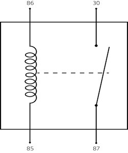
4-pin relays are typically used for simple on/off switching of a single circuit. They have two pins (85 and 86) for the control coil and two pins (30 and 87) for the switching contacts.
There are two main types of 4-pin relays:
- Normally Open (NO): In the default state, the contacts are open. When the coil is energized, the contacts close, completing the circuit.
- Normally Closed (NC): The contacts are closed in the default state. Energizing the coil opens the contacts, interrupting the circuit.
In a typical NO configuration, pin 85 connects to the positive side of the control circuit, and pin 86 connects to the negative or ground. Pin 30 connects to the positive side of the load circuit, and pin 87 connects to the load itself.
Understanding 5-Pin Relay Wiring Diagrams
5-pin relays add an extra contact (87a), allowing for switching between two circuits. Pin 87a is connected to the normally closed contact, while pin 87 is connected to the normally open contact. This enables a single relay to control two separate loads or switch between two different power sources.
When the coil is energized in a 5-pin relay, the normally open contact (87) closes, and the normally closed contact (87a) opens. This action switches the power from one circuit to the other.
Relay Protection: Safeguarding Your System
Relays can generate voltage spikes when deactivated due to the collapsing magnetic field. To protect sensitive components, diodes or resistors are often used to suppress these spikes. These protective devices provide a path for the excess voltage to dissipate harmlessly.
Practical Application: Control Relay Wiring in Automotive Lighting
A common example of control relay wiring is in automotive headlight circuits. The low-current signal from the headlight switch activates the relay coil, which then switches the high-current required for the headlights. This prevents overloading the headlight switch and ensures reliable operation.
Control and Relay Panels: Centralized Control Systems
Control and Relay Panels (CRPs) house multiple relays and other control components, providing a centralized location for managing complex electrical systems. CRPs are widely used in industrial settings for automation, power distribution, and process control. They often incorporate additional features like circuit breakers, fuses, and indicators for enhanced safety and monitoring.
Conclusion
Understanding control relay wiring diagrams is essential for anyone working with electrical systems. Whether you’re installing a simple automotive relay or designing a complex industrial control panel, a thorough grasp of these diagrams ensures proper functionality and safety. Remember to consult the specific datasheet for your chosen relay for detailed specifications and wiring instructions.