
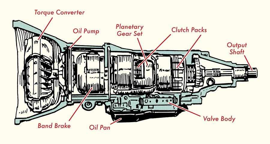
Automatic transmissions are marvels of engineering, seamlessly shifting gears without driver input. But how does this intricate system actually work? This article delves into the inner workings of an automatic transmission, providing a detailed explanation of its components and their interactions, aided by an Automatic Gearbox Diagram.
Understanding the purpose of a transmission is crucial. An engine operates efficiently within a specific speed range. A transmission acts as a power mediator, ensuring the engine runs optimally while providing the wheels with the necessary power for various driving conditions. It achieves this by adjusting gear ratios, which determine the relationship between engine speed and wheel speed. Unlike manual transmissions where the driver controls gear changes, automatic transmissions handle this process automatically.
A key component is the torque converter, responsible for transferring and multiplying engine power. It sits between the engine and transmission, enabling the engine to idle without moving the car. Let’s examine its inner workings:
- Pump (Impeller): Connected to the engine, the pump circulates transmission fluid outwards.
- Turbine: Driven by the fluid flow from the pump, the turbine is connected to the transmission input shaft.
- Stator (Reactor): Situated between the pump and turbine, the stator redirects fluid flow, multiplying torque and enhancing efficiency. Its one-way clutch ensures unidirectional fluid movement.
- Torque Converter Clutch: This clutch engages at higher speeds, locking the turbine and pump together for improved fuel economy.
The interplay of these components allows the torque converter to seamlessly transfer power. At low speeds, the stator multiplies torque, aiding acceleration. As speed increases, the torque converter clutch engages, creating a direct connection between the engine and transmission.
Planetary gear sets are the heart of automatic gear shifting. These ingenious mechanisms consist of a sun gear, planet gears (pinions) mounted on a carrier, and a ring gear. By selectively holding or driving these components, different gear ratios are achieved.
Brake bands and clutches control which components of the planetary gear set are engaged. Brake bands hold components stationary, while clutches connect them, enabling different gear ratios. Hydraulic pressure, controlled by valves and sensors, governs the engagement and disengagement of these components.
In summary, the power flow in an automatic transmission begins at the engine, transferring to the torque converter, then to the planetary gear sets via the transmission input shaft. The selective engagement of brake bands and clutches, controlled by hydraulic pressure, dictates the gear ratios and ultimately the vehicle’s speed and performance.
The automatic transmission is a complex system with intricate interactions between its components. Understanding the automatic gearbox diagram and the function of each part allows for a greater appreciation of the technology that enables smooth and effortless driving.