
Understanding your Audi A4’s stereo wiring diagram is crucial for any car audio upgrade or repair. European car manufacturers, including Audi, often use the ISO connector system, which can present some unique wiring challenges. This guide will delve into the intricacies of the Audi A4 Stereo Wiring Diagram, specifically focusing on the Gamma head unit, to help you navigate the process.
One common issue encountered when installing aftermarket stereos in an Audi A4 is reversed ignition logic. This means the red (typically switched power) and yellow (typically constant power) wires are swapped in the car’s wiring harness compared to the standard ISO wiring convention. Therefore, when connecting an aftermarket stereo, you’ll likely need to switch these two wires in the harness coming from your new head unit. This ensures the stereo receives constant power for memory functions and switched power for turning on and off with the ignition.
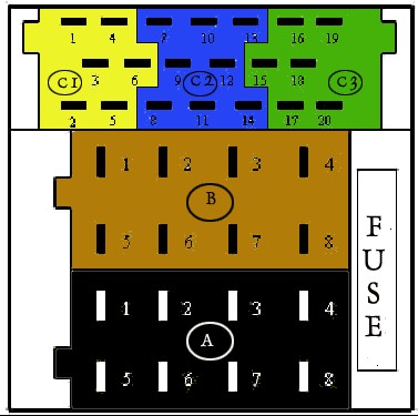
Addressing rear speaker connections in your Audi A4 can also be complex. If your vehicle lacks rear speakers or utilizes active speakers (powered by a separate amplifier), the wiring configuration differs. Active speaker systems, often associated with brands like Bose or Nokia, typically use a mini ISO connector. This connector is usually yellow and has 6 pins (designated as C1 in the diagram below).
The pin configuration for the yellow mini ISO connector (C1) on the back of the Gamma head unit is as follows:
- Pin 1: Left Rear Speaker Output
- Pin 2: Right Rear Speaker Output
- Pin 3: Ground (Shared by all 4 channels)
- Pin 4: Left Front Speaker Output
- Pin 5: Right Front Speaker Output
- Pin 6: Remote Turn-On Signal (For external amplifiers) Note: This pin isn’t always used; sometimes, the remote turn-on signal comes from pin 3 of the black 8-pin connector (A3).
Your Gamma head unit should have a sticker outlining the pin configuration. However, referencing the diagram above provides a visual aid for clarity.
To simplify the installation process, consider using an adapter specifically designed for Audi vehicles. The Autoleads PC 9401, for example, is compatible with several Audi models.
Various adapters cater to different Audi models and output voltages. Consult resources like Autoleads’ installation database (http://www.autoleads.co.uk/installation_db.html) for guidance on selecting the appropriate adapter.
If you prefer not to cut any factory wiring, the Autoleads PC 3433 offers a plug-and-play solution for connecting aftermarket stereos with female ISO connectors, like many Sony models.
Alternatively, choosing a head unit from Blaupunkt, which often uses mini ISO connectors, can streamline the installation process.
Successfully navigating your Audi A4’s stereo wiring diagram ensures a seamless audio upgrade experience. Remember to double-check wiring configurations and use appropriate adapters to avoid potential issues.