
This guide provides a detailed walkthrough on how to wire a 4-wire LED light bar switch, often used with MicTuning products, to a 2-wire LED light bar (typically with red positive and black negative wires). This installation, ideal for automotive enthusiasts, requires minimal experience and can be largely completed near the driver-side kick plate. You’ll leverage the mini-fuse block, a factory ground, and tap into an existing button for backlighting, resulting in a professional, factory-like setup. The process simplifies wiring, requiring only a single wire run to the LED light bar itself.
Understanding the 4-Wire LED Light Bar Switch and Wiring
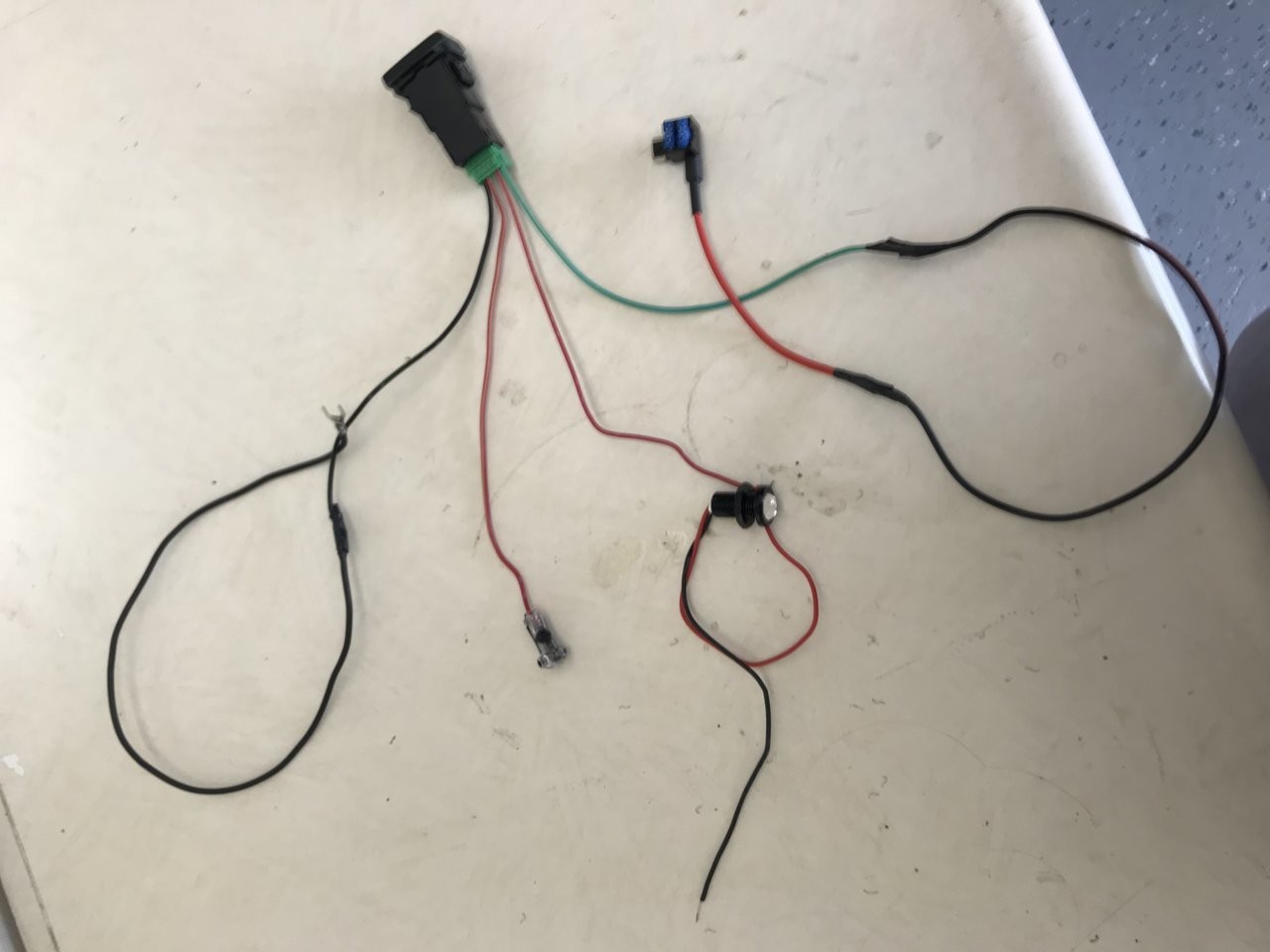
The MICTUNING LED Push Button Switch, a popular choice for this setup, features four wires:
- Black Wire (Ground): This wire needs to be grounded. Conveniently, a factory ground point is usually located behind the panel near the parking brake. A simple U-connector, attached to an extended black wire soldered to the switch, can be used for a secure connection.
- Red Wire (Adjacent to Black – Illumination): This wire powers the backlit text on the switch. To achieve illumination when the headlights are on, tap into the power source of a nearby button that activates with the headlights. A T-tap connector is recommended for a non-destructive connection to a suitable power source, such as the cargo lamp wire.
- Red Wire (Trigger): This wire activates the relay for the LED light bar. Extend this wire through the firewall, preferably above the brake pedal, into the engine bay. This extended wire will connect to the relay’s trigger wire. Using an inline fuse for protection is strongly advised.
- Green Wire (Switch Power): This wire provides power to the switch’s trigger function. Use a low-profile mini add-a-fuse to tap into a suitable fuse, such as the 15A rear parking light fuse in the driver-side fuse box.
Grounding the LED Light Bar
The black wire from the LED light bar needs to be grounded. Find a suitable factory ground point in the engine bay for this connection. It’s not necessary to run this ground wire back to the cab.
Functionality Test
After completing the wiring, test the setup:
- Headlights ON: The switch’s text should illuminate, but the LED light bar should remain off.
- Switch ON: With headlights on, pressing the switch should illuminate the LED light bar icon and turn on the light bar.
- Headlights OFF: The light bar should stay on, but the switch text should turn off. Only the light bar icon will remain illuminated.
- Switch OFF: Everything should turn off.
Choosing the Correct Add-a-Fuse
When using the driver-side fuse box, it’s crucial to use low-profile mini add-a-fuses. Standard add-a-fuses are too large for this fuse box. Ensure you purchase the correct type for compatibility. ABN Fuse Tap Fuse Holders are a good option.
This comprehensive guide simplifies the 4 Wire Led Light Wiring Diagram, enabling a clean and functional installation. By following these steps and understanding the function of each wire, you can successfully integrate your new LED light bar with a professional finish. Remember to prioritize safety by using inline fuses and ensuring secure connections.