
The “OL” display on a digital multimeter, often referred to as a 0l Multimeter, signifies an over-range condition. This dates back to the 1970s when affordable 199.9 mV LCD voltmeter modules first became available. These modules, featuring a seven-segment display with decimal points in a 1.9.9.9 format, had a maximum displayable voltage of 199.9 mV. Early multimeters utilized these modules alongside designs published in electronics magazines like Electronics Today International.
Over-range indications were limited by the seven-segment display capabilities, resulting in displays like 1 or the more common OL. Electrically, “OL” simply meant the module received a voltage exceeding 199.9 mV. In resistance measurement mode, a multimeter uses a current source to pass current through the resistor being tested. The voltage drop across the resistor is then measured. An open circuit, offering infinite resistance, results in a voltage exceeding the meter’s maximum input, triggering the “OL” display.
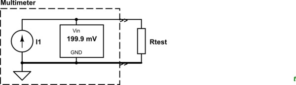 Simplified resistance measurement circuit
Figure 1. A simplified schematic of a resistance measurement circuit. The current source (I1) is set to approximately 0.1 mA for the 2 kΩ range.
While datasheets for these early displays are scarce, “OL” likely stands for OverLoad, indicating the input voltage surpasses the meter’s measurement capacity. Interestingly, these early 9V multimeters often had a 0V ground approximately 2.5V below the +9V input. This allowed users to cleverly check the battery voltage by measuring the difference between the positive and negative terminals on the 20 VDC range. For example, a reading of +2.5V on the positive terminal and -6.2V on the negative terminal indicates a battery voltage of 8.7V. This technique might also work on some modern digital multimeters. The “OL” reading on a 0L multimeter, therefore, serves as a crucial indicator of an over-range condition, prompting the user to adjust the measurement range or investigate a potential open circuit in the tested component.